- 您现在的位置:买卖IC网 > Sheet目录187 > 4310R-101-222 (Bourns Inc.)RES ARRAY 2.2K OHM 9 RES 10-SIP
Features
■ RoHS compliant* versions available (see
How to Order “Termination” option)
■ Now available with improved tolerance
to ±0.5 %
–82 0 –10
431
C11
3 2
R
11
■ Low pro?le provides compatibility with
DIPs
■ Compatible with automatic insertion
equipment
■ Superior package integrity
4300R Series - Thick Film Molded SIPs
Product Characteristics
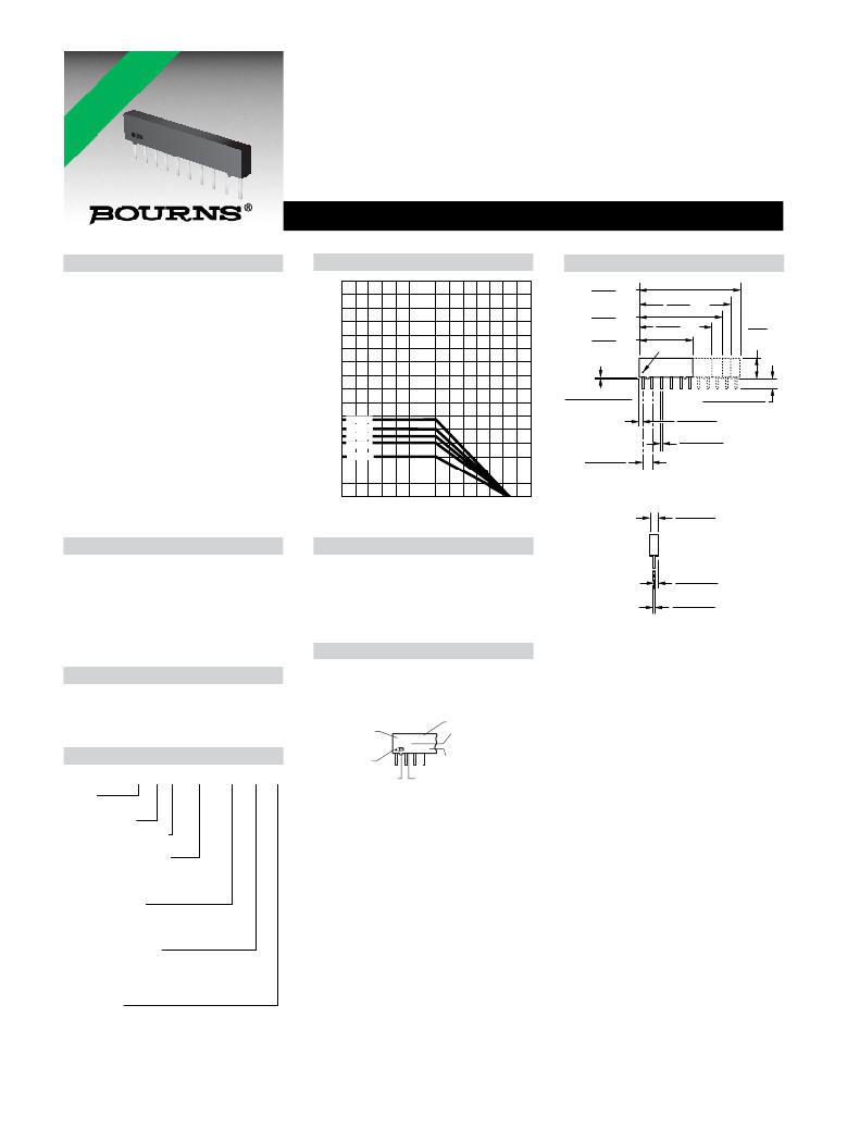
Package Power Temp. Derating Curve
Product Dimensions
MAX.
MAX.
MAX.
MAX.
Resistance Range
.................... 10 ohms to 10 megohms
Maximum Operating Voltage .........100 V
Temperature Coef?cient of Resistance
50 Ω to 2.2 megohms.....±100 ppm/°C
below 50 Ω .....................±250 ppm/°C
above 2.2 megohms.......±250 ppm/°C
TCR Tracking.........................50 ppm/°C
3.50
3.00
2.50
27.53
(1.084)
22.45
(.884)
14.83 MAX.
(.584)
24.99
(.984)
19.92
(.784)
PIN #1 REF.
4.95
(.195)
MAX.
maximum; equal values
Resistor Tolerance ............... See circuits
Operating Temperature
................................-55 °C to +125 °C
Power Rating ................... Derate to zero
power from + 70 °C to + 125 °C
Insulation Resistance
................ 10,000 megohms minimum
Dielectric Withstanding Voltage
2.00
1.50
1.00
.50
4311R
4310R
4309R
4308R
4306R
.407 + .102/ - .000
(.016 + .004/ - 000)
2.54 .07
(.100 .003*)
TYP.
NON-ACCUM.
1.02
(.040
.483
(.020
3.43 + .38/ - .25
(.135 + .015/ - .010)
.12
.005)
.050
TYP.
.002)
...........................................200 VRMS
Lead Solderability .....Meet requirements
0
25
70 125
AMBIENT TEMPERATURE ( ° C )
2.16 .10
of MIL-STD-202 Method 208
Environmental Characteristics
TESTS PER MIL-STD-202 ...... ?R MAX.
Package Power Rating at 70 °C
4306R .....................................0.75 watts
(.085 .004)
Short Time Overload..................±0.25 %
Load Life ....................................±1.00 %
Moisture Resistance ..................±0.50 %
Resistance to Soldering Heat
...............................................±0.25 %
4308R .....................................1.00 watts
4309R .....................................1.13 watts
4310R .....................................1.25 watts
4311R .....................................1.38 watts
1.02
(.0425
.254
(.010
.05
.002)
.050
.002)
Terminal Strength ......................±0.25 %
Thermal Shock ..........................±0.25 %
Physical Characteristics
Flammability ........ Conforms to UL94V-0
Lead Frame Material
Typical Part Marking
Represents total content. Layout may
vary. Marking may be truncated on
shorter versions due to size constraints.
Governing dimensions are in metric. Dimensions in parentheses
are inches and are approximate.
*Terminal centerline to centerline measurements made at point of
emergence of the lead from the body.
.........................Copper, solder coated
Body Material.................. Novolac epoxy
How To Order
PART
NUMBER
PIN ONE
INDICATOR
4310R-102
-823
CYYWW
CIRCUIT
RESISTANCE
CODE
DATE CODE
43 06 R - 101 - 222 __ __
Model
(43 = Molded SIP)
MANUFACTURER'S
TRADEMARK
COUNTRY OF MANUFACTURE
(C = COSTA RICA)
Number of Pins
Physical Con?guration
(R = Thick Film Low Pro?le)
Electrical Con?guration
? 101 = Bussed
? 102 = Isolated
? 104 = Dual Terminator
Resistance Code
? First 2 digits are signi?cant
? Third digit represents the
number of zeros to follow.
Resistance Tolerance
? Blank = ±2 % (see “Resistance Tolerance”
on next page for resistance range)
? F = ±1 % (100 ohms - 1 megohm)
? D = ±0.5 % (100 ohms - 1 megohm)
Terminations
? All electrical con?gurations EXCEPT 104:
LF = Tin-plated (RoHS compliant version)
? ONLY electrical con?guration 104:
L = Tin-plated (RoHS compliant version)
? Blank = Tin/Lead-plated
Consult factory for other available options.
For Standard Values Used in
Capacitors, Inductors, and Resistors,
*RoHS Directive 2002/95/EC Jan. 27, 2003 including annex and RoHS Recast 2011/65/EU June 8, 2011.
Speci?cations are subject to change without notice.
Customers should verify actual device performance in their speci?c applications.
发布紧急采购,3分钟左右您将得到回复。
相关PDF资料
4384-6
BOX PLASTIC W/GUIDES & COVER BLU
4416P-2-203
RES ARRAY 20K OHM 15 RES 16-SOIC
445W35W35M00000
CRYSTAL 35.00000 MHZ 10PF SMD
44EN14-10
SEALED AERO SWITCH
450-019
CONN BOOT STRAIN RELIEF RED
450-024
CONN BOOT STRAIN RELIEF CLEAR
45719-0008
CONN POWER EDGE 6POS VERT PCB
45AYP6C
FILTER 3-PHASE RFI SINGLE 45A
相关代理商/技术参数
4310R-101-222FLF
制造商:Bourns Inc 功能描述:Res Thick Film NET 2.2K Ohm 1% 1.25W ±100ppm/°C BUS Molded 10-Pin SIP Pin Thru-Hole
4310R-101-222LF
功能描述:电阻器网络与阵列 2.2K 10Pin 2% Bussed RoHS:否 制造商:Vishay/Thin Film 产品类型:Networks 电路类型:Divider 电阻器数量: 电阻数值:10 kOhms 容差:0.1 % 温度系数: 管脚数量:3 工作温度范围:- 55 C to + 155 C 尺寸:1.02 mm W x 3.05 mm L x 1.4 mm H 引线间隔: 端接类型:SMD/SMT 封装:Reel
4310R-101-222LF
制造商:Bourns Inc 功能描述:RESISTOR BUS RES N/W 9 2.2KOHM 2% SI 制造商:Bourns Inc 功能描述:RESISTOR, BUS RES N/W 9, 2.2KOHM, 2%, SIP
4310R101223
制造商:BOU 功能描述:SRN10B322 BOURNS NXF8B
4310R-101-223
功能描述:电阻器网络与阵列 22K 10Pin 2% Bussed RoHS:否 制造商:Vishay/Thin Film 产品类型:Networks 电路类型:Divider 电阻器数量: 电阻数值:10 kOhms 容差:0.1 % 温度系数: 管脚数量:3 工作温度范围:- 55 C to + 155 C 尺寸:1.02 mm W x 3.05 mm L x 1.4 mm H 引线间隔: 端接类型:SMD/SMT 封装:Reel
4310R-101-223LF
功能描述:电阻器网络与阵列 22K 10Pin 2% Bussed RoHS:否 制造商:Vishay/Thin Film 产品类型:Networks 电路类型:Divider 电阻器数量: 电阻数值:10 kOhms 容差:0.1 % 温度系数: 管脚数量:3 工作温度范围:- 55 C to + 155 C 尺寸:1.02 mm W x 3.05 mm L x 1.4 mm H 引线间隔: 端接类型:SMD/SMT 封装:Reel
4310R-101-223LF
制造商:Bourns Inc 功能描述:RESISTOR BUS RES N/W 9 22KOHM 2% SI 制造商:Bourns Inc 功能描述:RESISTOR, BUS RES N/W, 9, 22KOHM, 2%, SIP
4310R-101-224
功能描述:电阻器网络与阵列 220K 10Pin 2% Bussed RoHS:否 制造商:Vishay/Thin Film 产品类型:Networks 电路类型:Divider 电阻器数量: 电阻数值:10 kOhms 容差:0.1 % 温度系数: 管脚数量:3 工作温度范围:- 55 C to + 155 C 尺寸:1.02 mm W x 3.05 mm L x 1.4 mm H 引线间隔: 端接类型:SMD/SMT 封装:Reel
